Tuesday


VTP

Before you add any switch to the network you need to get in the habit of checking the VTP configuration and make sure the VTP Configuration Revision number is set to 0. You can do this by console in to the switch and type in sho vtp status, if the revision is not 0 then do write erase and reload. This will put your switch to manufacture default. If you don’t do that and the Configuration Revision on your network switches is lower then your new switches your Vlan nodes will be down and you just created a big problem.
SW1#sho vtp status
VTP Version : 2
Configuration Revision : 0
Maximum VLANs supported locally : 255
Number of existing VLANs : 5
VTP Operating Mode : Server
VTP Domain Name : ciscosteps
VTP Pruning Mode : Disabled
VTP V2 Mode : Disabled
VTP Traps Generation : Disabled
MD5 digest : 0x7D 0x5A 0xA6 0x0E 0x9A 0x72 0xA0 0x3A
Configuration last modified by 0.0.0.0 at 0-0-00 00:00:00
Local updater ID is 0.0.0.0 (no valid interface found)
VTP Server:
- Power to change vlan info
- sends and receive VTP updates
- saves Vlan config
======================================================
SW2#sho vtp status
VTP Version : 2
Configuration Revision : 0
Maximum VLANs supported locally : 255
Number of existing VLANs : 5
VTP Operating Mode : Client
VTP Domain Name : ciscosteps
VTP Pruning Mode : Disabled
VTP V2 Mode : Disabled
VTP Traps Generation : Disabled
MD5 digest : 0x7D 0x5A 0xA6 0x0E 0x9A 0x72 0xA0 0x3A
Configuration last modified by 0.0.0.0 at 0-0-00 00:00:00
VTP Client:
- can't change vlan info
- sends and receive VTP updates
- does not save Vlan config
=======================================================
SW3#sho vtp status
VTP Version : 2
Configuration Revision : 0
Maximum VLANs supported locally : 255
Number of existing VLANs : 5
VTP Operating Mode : Transparent
VTP Domain Name : ciscosteps
VTP Pruning Mode : Disabled
VTP V2 Mode : Disabled
VTP Traps Generation : Disabled
MD5 digest : 0x7D 0x5A 0xA6 0x0E 0x9A 0x72 0xA0 0x3A
Configuration last modified by 0.0.0.0 at 0-0-00 00:00:00
VTP Transparent:
- Power to change vlan info
- forwards VTP updates
- does not listen to VTP updates
- saves Vlan config
Monday
configuring L3 etherChannel

Switch(config)#inter port-channel 12
Switch(config-if)#no switchport --> This command changes the interface from L2 to L3
Switch(config-if)#ip address 12.0.0.1 255.255.255.0
Switch(config-if)#no shut
Switch(config-if)#end
Switch#
Switch#ping 12.0.0.2--> the other ether-channel on SW2
Sending 5, 100-byte ICMP Echos to 12.0.0.2, timeout is 2 seconds:
!!!!!
Success rate is 100 percent (5/5), round-trip min/avg/max = 1/2/5 ms
--------------------------------------------------------------------------
Switch#sho etherchannel
Channel-group listing:
----------------------
Group: 12
----------
Group state = L2
Ports: 2 Maxports = 16
Port-channels: 1 Max Port-channels = 16
Protocol: LACP
Switch#sho etherchannel summ
Switch#sho etherchannel summary
Flags: D - down P - in port-channel
I - stand-alone s - suspended
H - Hot-standby (LACP only)
R - Layer3 S - Layer2
U - in use f - failed to allocate aggregator
u - unsuitable for bundling
w - waiting to be aggregated
d - default port
Number of channel-groups in use: 1
Number of aggregators: 1
Group Port-channel Protocol Ports
------+-------------+-----------+----------------------------------------------
12 Po12(SU) LACP Fa0/1(P) Fa0/2(P)
--------------------------------------------------------------------------
Switch#sho interfaces etherchannel
FastEthernet0/1:
Port state = 1
Channel group = 12 Mode = Active Gcchange = -
Port-channel = Po12 GC = - Pseudo port-channel = Po12
Port index = 0 Load = 0x00 Protocol = LACP
Flags: S - Device is sending Slow LACPDUs F - Device is sending fast LACPDUs
A - Device is in active mode. P - Device is in passive mode.
Local information:
LACP port Admin Oper Port Port
Port Flags State Priority Key Key Number State
Fa0/1 SA down 32768 0x0 0x0 0x1
Partner's information:
LACP port Admin Oper Port Port
Port Flags Priority Dev ID Age key Key Number State
Fa0/1 SA 32768 00E0.B080.DED2 0x0 0x0 0x1
Age of the port in the current state: 00d:02h:10m:50s
FastEthernet0/2:
Port state = 1
Channel group = 12 Mode = Active Gcchange = -
Port-channel = Po12 GC = - Pseudo port-channel = Po12
Port index = 0 Load = 0x00 Protocol = LACP
Flags: S - Device is sending Slow LACPDUs F - Device is sending fast LACPDUs
A - Device is in active mode. P - Device is in passive mode.
Local information:
LACP port Admin Oper Port Port
Port Flags State Priority Key Key Number State
Fa0/2 SA down 32768 0x0 0x0 0x2
Partner's information:
LACP port Admin Oper Port Port
Port Flags Priority Dev ID Age key Key Number State
Fa0/2 SA 32768 00E0.B080.DED2 0x0 0x0 0x2
Age of the port in the current state: 00d:02h:10m:50s
----
Port-channel12:Port-channel12 (Primary aggregator)
Age of the Port-channel = 00d:00h:30m:58s
Logical slot/port = 2/12 Number of ports = 2
HotStandBy port = null
Port state =
Protocol = 1
Port Security = Disabled
Ports in the Port-channel:
Index Load Port EC state No of bits
------+------+------+------------------+-----------
0 00 Fa0/1 Active 0
0 00 Fa0/2 Active 0
Time since last port bundled: 00d:02h:10m:50s Fa0/2
configuring L2 etherChannel

Switch#config t
Switch(config)#int range fa0/1 - 2
Switch(config-if-range)#channel-protocol ?
lacp Prepare interface for LACP protocol
pagp Prepare interface for PAgP protocol
Switch(config-if-range)#channel-protocol lacp
Switch(config-if-range)#channel-group 12 ?
mode Etherchannel Mode of the interface
Switch(config-if-range)#channel-group 12 mode ?
active Enable LACP unconditionally
auto Enable PAgP only if a PAgP device is detected
desirable Enable PAgP unconditionally
on Enable Etherchannel only
passive Enable LACP only if a LACP device is detected
Switch(config-if-range)#channel-group 12 mode active ?
<cr>
Switch(config-if-range)#channel-group 12 mode active
%LINK-5-CHANGED: Interface Port-channel 12, changed state to up
%LINEPROTO-5-UPDOWN: Line protocol on Interface Port-channel 12, changed state to up
Switch(config-if-range)#end
------------------------------------------------------------------------------------
Switch#sho ip int b | inc up
Interface IP-Address OK? Method Status Protocol
FastEthernet0/1 unassigned YES unset up up
FastEthernet0/2 unassigned YES unset up up
Port-channel 12 unassigned YES unset up up
Switch#
Switch#sho etherchannel
Channel-group listing:
----------------------
Group: 12
----------
Group state = L2
Ports: 2 Maxports = 16
Port-channels: 1 Max Port-channels = 16
Protocol: LACP
------------------------------------------------------------------------------------
Switch#sho etherchannel port-channel
Channel-group listing:
----------------------
Group: 12
----------
Port-channels in the group:
---------------------------
Port-channel: Po12 (Primary Aggregator)
------------
Age of the Port-channel = 00d:00h:17m:39s
Logical slot/port = 2/12 Number of ports = 2
GC = 0x00000000 HotStandBy port = null
Port state = Port-channel
Protocol = LACP
Port Security = Disabled
Ports in the Port-channel:
Index Load Port EC state No of bits
------+------+------+------------------+-----------
0 00 Fa0/1 Active 0
0 00 Fa0/2 Active 0
Time since last port bundled: 00d:00h:15m:41s Fa0/2
Switch#
Spanning Tree

Switch#sho spanning-tree
VLAN0001
Spanning tree enabled protocol ieee
Root ID Priority 32769
Address 00D0.5825.5C01
Cost 19
Port 1(FastEthernet0/1)
Hello Time 2 sec Max Age 20 sec Forward Delay 15 sec
Bridge ID Priority 32769 (priority 32768 sys-id-ext 1)
Address 00E0.B080.DED2
Hello Time 2 sec Max Age 20 sec Forward Delay 15 sec
Aging Time 20
Interface Role Sts Cost Prio.Nbr Type
---------------- ---- --- --------- -------- --------------------------------
Fa0/2 Altn BLK 19 128.2 P2p
Fa0/1 Root FWD 19 128.1 P2p
Basic Vlan config

Switch>en
Switch#config t
Switch(config)#int fa0/12
Switch(config-if)#switchport mode access
Switch(config-if)#switchport access vlan 12
% Access VLAN does not exist. Creating vlan 12
Switch(config-if)#int fa0/13
Switch(config-if)#switchport mode access
Switch(config-if)#switchport access vlan 13
% Access VLAN does not exist. Creating vlan 13
------------------------------------------------------------------
Switch>en
Switch#config t
Enter configuration commands, one per line. End with CNTL/Z.
Switch(config)#int fa0/1
Switch(config-if)#switchport mode trunk
Switch(config-if)#end
Switch#
Switch#sho interfaces trunk
Port Mode Encapsulation Status Native vlan
Fa0/1 on 802.1q trunking 1
Port Vlans allowed on trunk
Fa0/1 1-1005
Port Vlans allowed and active in management domain
Fa0/1 1,12,13
Port Vlans in spanning tree forwarding state and not pruned
Fa0/1 1,12,13
-------------------------------------------------------------------
Switch#sho vlan
VLAN Name Status Ports
---- -------------------------------- --------- -------------------------------
1 default active Fa0/2, Fa0/3, Fa0/4, Fa0/5
Fa0/6, Fa0/7, Fa0/8, Fa0/9
Fa0/10, Fa0/11, Fa0/14, Fa0/15
Fa0/16, Fa0/17, Fa0/18, Fa0/19
Fa0/20, Fa0/21, Fa0/22, Fa0/23
Fa0/24, Gig1/1, Gig1/2
12 VLAN0012 active Fa0/12
13 VLAN0013 active Fa0/13
1002 fddi-default act/unsup
1003 token-ring-default act/unsup
1004 fddinet-default act/unsup
1005 trnet-default act/unsup
Tuesday


Saturday

Tuesday
OSPF LSA Types
Type 1 LSA - it build the graph for intra-area SPF
TO VERIFY : sho ip ospf database router [id]
Type 2 LSA - Generated by DR on broadcast and non broadcast network type
TO VERIFY : sho ip ospf database NETWORK [link ID] for DR
Type 3 LSA - Generated by ABR to summarize the topology to move traffic from area 0 to area 1 with out running SPF
example :
ABR can reach link 1 via SPF w/ the cost of 50
I can reach the ABR via SPF of 10 in my area
to reach link 1 via SPF in cost of 50+10 . this why inter-area is called DV (DISTANCE VICTOR)
TO VERIFY : sho ip ospf database summary [link ID]
Type 4 LSA - ASBR summary - Generated by ABR and describes the ABR reach-ability to ASBR, it does include cost but hides ABR's as actual path to destination
TO VERIFY : sho ip ospf database asbr-summary [link ID]
Type 5 LSA - Generated by ASBR and describe routes the ASBR is redistributing
example: R1 run SPF cost of 5 to reach ABR, ABR runs SPF of 10 to reach ASBR, ASBR run cost of 15 to reach external route
R1's one cost to reach the external is 5+10+15
so if you look @ the topology LSA type 4 describe how to reach the ASBR and type 5 LSA provide the cost to the outside network
TO VERIFY : sho ip ospf database external [link ID]
- Describe their connected links
- What are the cost of the links
- What are the neighbors that are adjacent on the links
TO VERIFY : sho ip ospf database router [id]
Type 2 LSA - Generated by DR on broadcast and non broadcast network type
- Not flooded outside the area they originated in :
- The LSA will not move to the ABR
TO VERIFY : sho ip ospf database NETWORK [link ID] for DR
Type 3 LSA - Generated by ABR to summarize the topology to move traffic from area 0 to area 1 with out running SPF
example :
ABR can reach link 1 via SPF w/ the cost of 50
I can reach the ABR via SPF of 10 in my area
to reach link 1 via SPF in cost of 50+10 . this why inter-area is called DV (DISTANCE VICTOR)
TO VERIFY : sho ip ospf database summary [link ID]
Type 4 LSA - ASBR summary - Generated by ABR and describes the ABR reach-ability to ASBR, it does include cost but hides ABR's as actual path to destination
- ABR can reach ASBR via SPF w/ the cost of 50
- I can reach the ABR via SPF of 10 in my area
- I can reach ASBR via SPF in cost of 50+10 this why intra-area is called DV (DISTANCE VICTOR)
TO VERIFY : sho ip ospf database asbr-summary [link ID]
Type 5 LSA - Generated by ASBR and describe routes the ASBR is redistributing
example: R1 run SPF cost of 5 to reach ABR, ABR runs SPF of 10 to reach ASBR, ASBR run cost of 15 to reach external route
R1's one cost to reach the external is 5+10+15
so if you look @ the topology LSA type 4 describe how to reach the ASBR and type 5 LSA provide the cost to the outside network
TO VERIFY : sho ip ospf database external [link ID]
Saturday
DR / BDR / DROther
- Desinated Router ( DR )
- used on broadcast links to minimize adjacencies and LSA replication
- Backup Designated Router ( BDR )
- Used for redundancy of DR
- DROthers
- For all other routers on the network
- form adjacency w/ DR & BDR
- Stop at 2-way adjacency with each other
- The DR and BDR are chosen through election process
- DROther send LSUs to DR/BDR via multicast 224.0.0.6
- DR forwards LSUs to DROthers via multicast 224.0.0.5
- Prevents repeated forwarding of unneeded LSAs on the network
- BDR does not forward LSUs , it only waits for DR to fail
OSPF Network Types
- Broadcast ==> Ethernet
- Non Broadcast ===> ATM or Frame-relay
- Point - to - Point ===> HDLC or PPP
- Point-to-Multipoint ===> work around for ATM and Frame-relay design
- Point-to-Multipoint Non Broadcast ===> work around for ATM and Frame-relay design
- loopback ==> used for software loopbacks
Thursday
OSPF Stub area, totally stubby and NSSA
multiple-area OSPF on a router

this is standard ospf out put from sho ip osp neighbor and router and if you look at R2 they are no inter-area routes

The command to configure stubby area is as follow:
R2(config)# router ospf 1
R2(config-router)# area 23 stub
R3(config)# router ospf 1
R3(config-router)# area 23 stub
R2(config-router)# area 23 stub
R3(config)# router ospf 1
R3(config-router)# area 23 stub


The command to configure totally stubby areais as follow:
Enter the stub no-summary command on R2 (the ABR) under the OSPF process.
R2(config)# router ospf 1
R2(config-router)# area 23 stub no-summary

Now will discus NSSA.
To generate an external route into the NSSA, use the redistribute connected subnets command on R3. This adds the previously unreachable loopback 20 into OSPF. Be sure to include the subnets keyword; otherwise, only classful networks are redistributed.
R2(config)# router ospf 1
R2(config-router)# no area 23 stub
R2(config-router)# area 23 nssa
R3(config)# router ospf 1
R3(config-router)# no area 23 stub
R3(config-router)# area 23 nssa
R3(config-router)# redistribute connected subnets
after the config on R2 and R3 as ASSA we come up w/ the following out out when sho ip osp command is typed on R2 (it will be the same on R3) :

Nlet look at routing table for each router and see what happen . lets type show ip route on R2. Notice that the external route comes in as type N2 from R3. This is because it is a special NSSA external route
 Now lets do show ip route output on R1. Notice that the route is now a regular E2 external route, because R2 has performed the type 7 to type 5 translation and R3 no longer has a default route in it, but inter-area routes are coming in.
Note: An NSSA does not have the default route injected by the ABR (R2) automatically. It is possible to make the ABR inject the default route into the NSSA using the area 23 nssa default-information-originate command on R2
To generate an external route into the NSSA, use the redistribute connected subnets command on R3. This adds the previously unreachable loopback 20 into OSPF. Be sure to include the subnets keyword; otherwise, only classful networks are redistributed.
R2(config)# router ospf 1
R2(config-router)# no area 23 stub
R2(config-router)# area 23 nssa
R3(config)# router ospf 1
R3(config-router)# no area 23 stub
R3(config-router)# area 23 nssa
R3(config-router)# redistribute connected subnets
after the config on R2 and R3 as ASSA we come up w/ the following out out when sho ip osp command is typed on R2 (it will be the same on R3) :

Nlet look at routing table for each router and see what happen . lets type show ip route on R2. Notice that the external route comes in as type N2 from R3. This is because it is a special NSSA external route

Note: An NSSA does not have the default route injected by the ABR (R2) automatically. It is possible to make the ABR inject the default route into the NSSA using the area 23 nssa default-information-originate command on R2
Monday
Route Summarization Calculation Example
Networks to summarize :We are using /24
172.16.8.0
172.16.9.0
172.16.10.0
172.16.11.0
172.16.12.0
172.16.13.0
172.16.14.0
172.16.15.0
172.16.16.0
172.16.17.0
172.16.18.0
172.16.19.0
first we need addresses converted to binary format:
(in this example the changes occurs on the 3rd octet )
00001000 =8
00001001 =9
00001010 =10
00001011 =11
00001100 =12
00001101 =13
00001110 =14
00001111 =15
00010000 =16
00010000 =17
00010001 =18
00010011 =19
we need to locate the ON=1 bits at which the common pattern of digits ends
00001|000 =8
00001|001 =9
00001|010 =10
00001|011 =11
00001|100 =12
00001|101 =13
00001|110 =14
00001|111 =15
0001|0000 =16
0001|0000 =17
0001|0001 =18
0001|0011 =19
Now lets look for summary address(es) !!!
00001 = 8
0001 = 16
now let put this 2 numbers on the 3rd octet of the Ip
AHA !!! we have 2 summary addresses
172.16.8.0 and 172.16.16.0
Now we need to find out the subnet masks for this 2 Ip.
Locate the bit where the common pattern of digits ends for the 2 Ips.
00001|000 =8
00001|001 =9
00001|010 =10
00001|011 =11
00001|100 =12
00001|101 =13
00001|110 =14
00001|111 =15
000100|00 =16
000100|00 =17
000100|01 =18
000100|11 =19
The first 21 bits of the IP addresses from 172.16.8.0 through 172.16.15.0 Therefore /21
The first 22 bits of the IP addresses from 172.16.16.0 through 172.16.19.0 Therefore /22.
And we use this value as a 3rd octet in our net-mask
So :
172.16.8.0 255.255.248.0
172.16.16.0 255.255.252.0
Its our summarized routes / networks.
Sunday
OSPF Point-to-Multipoint


What we have here is an OSPF network on non broadcast, by default when you configure the frame relay interfaces, all of them will be in network type NON BROADCAST. We also left the OSPF priority on the interfaces to default. As you see the router with highest Ip wins to be a DR.

In the second scenario we only going to use the OSPF Point to Multipoint command on R2 and see what is the behavior of the network. All frame relay interfaces are in default priority and watch the adjacency

In the third scenario we only going to use the ospf point to multipoint command on all the 3 interfaces and see what the behavior of the network is this time and watch the adjacency. All frame relay interfaces are in default priority

Saturday
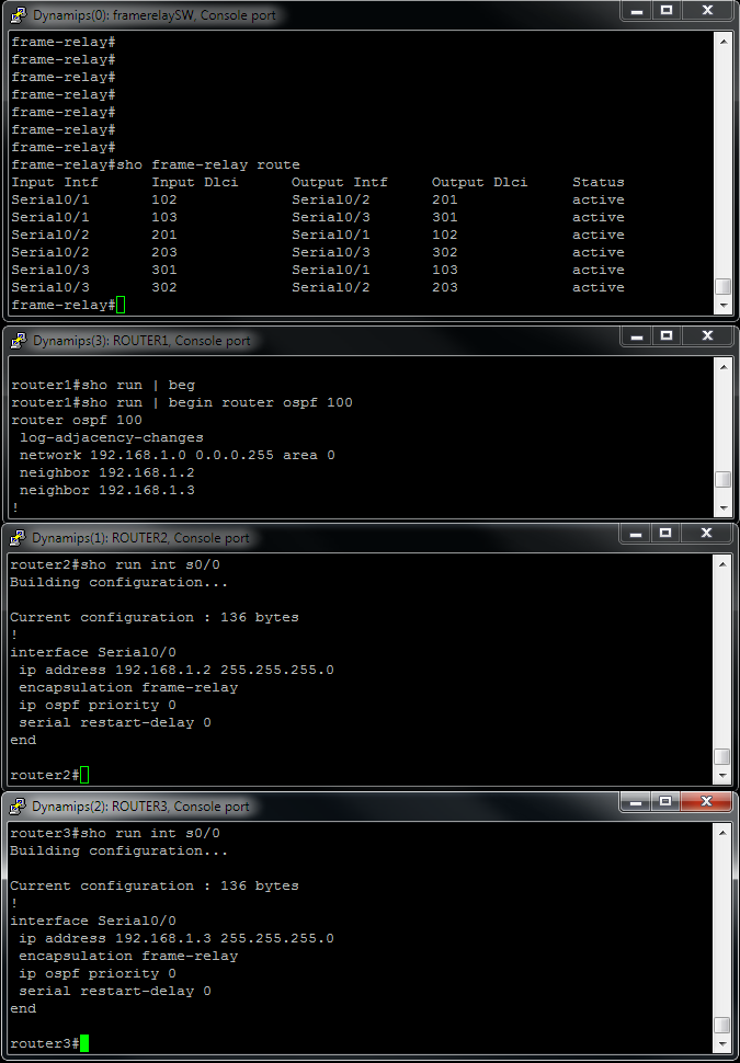
OSPF config On None Broadcast Mode over Frame-Relay

All 3 routers are using the default none broadcast mode on their frame-relay interfaces, so neighboring routers must be manually configured on DR, in this case is R1. We manually changed the OSPF priority on the interface level with the command ip ospf priority 0 on R2 and R3 so router 1 can become a DR

Subscribe to:
Comments (Atom)